
In Short: What This Article Is About
Proportional hydraulic valves and directional valves are used in lifts, elevators, presses, hydraulic power units, special machinery, test benches and many other systems where pressure, flow or movement direction has to be controlled smoothly.
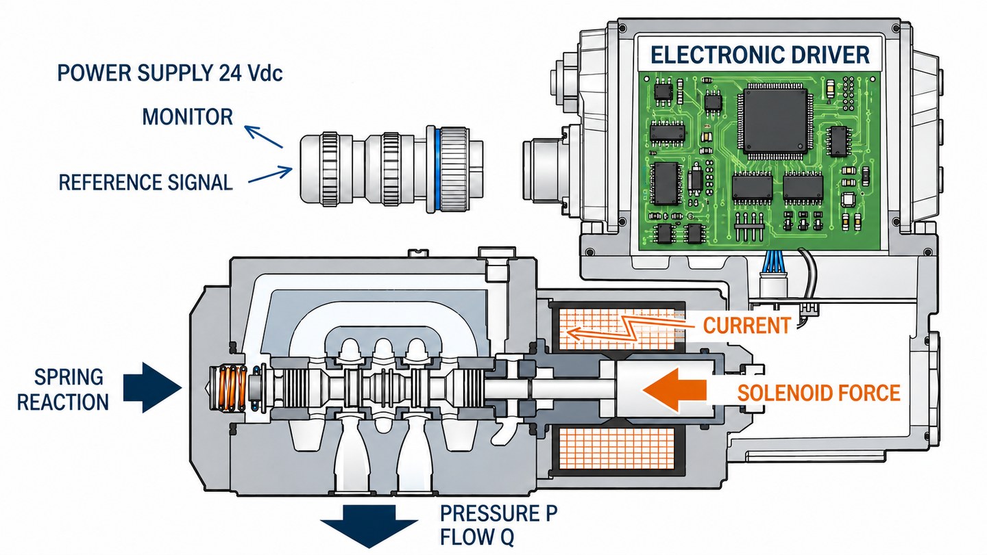
For control, a proportional valve needs not a voltage source, but a current amplifier. Coil current creates the magnetic force, and that force moves the armature, plunger or spool.
The main chain is:
command signal -> amplifier -> coil current -> magnetic force -> valve position -> flow or pressure.
This article explains how it works, which parameters really matter when choosing an amplifier, what Imin, Imax, dither, ramp and PWM mean, and how to understand whether a specific driver can replace an old module.
At the end, we will show which tasks VL-PVD1-24 is suited for: a configurable VlasovLab current driver for controlling one coil of a proportional valve or directional valve.
1. What a Proportional Valve Is
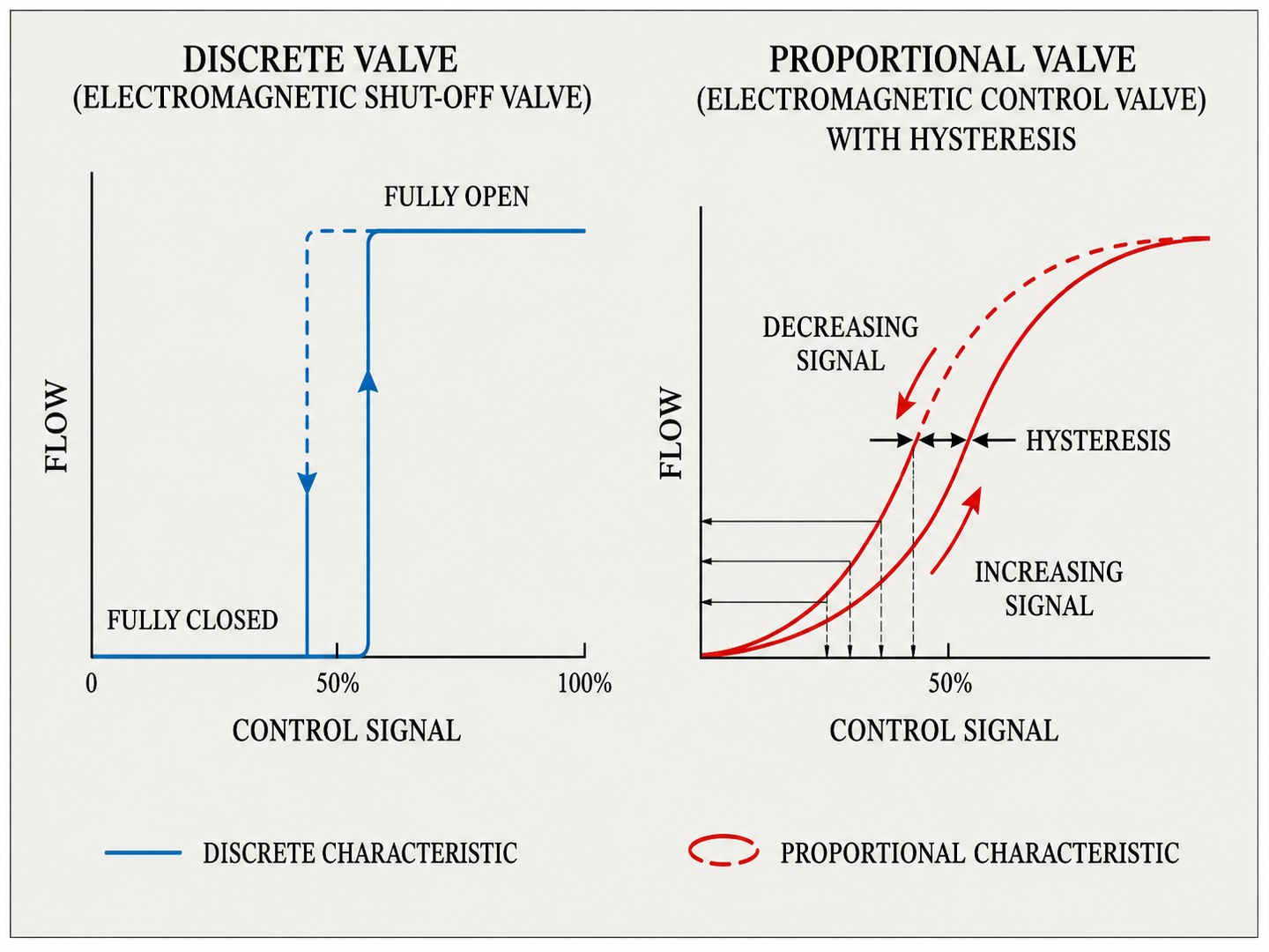
A conventional discrete hydraulic valve works roughly like a switch: either open or closed. This is convenient for simple tasks, but it is poorly suited where smooth movement, soft start, cylinder speed control, pressure limiting or flow control without sharp jumps is required.
A proportional valve works differently. Its working position depends on the control action. Usually this is the current through the solenoid coil. The higher the current, the higher the magnetic force. This force moves the armature, plunger or spool, which changes the flow area, pressure or flow distribution.
At the same time, it is wrong to think that every proportional valve is perfectly linear. Real hydraulics has friction, springs, hydrodynamic forces, part tolerances, oil viscosity, temperature, contamination and spool overlap. That is why the amplifier is needed not only for "power", but also for proper adjustment of valve behavior.
Main groups of proportional valves:
| Valve type | What it controls | Example tasks |
|---|---|---|
| Proportional pressure valve | Pressure or pressure limiting | clamping, braking, force limiting, smooth line pressure |
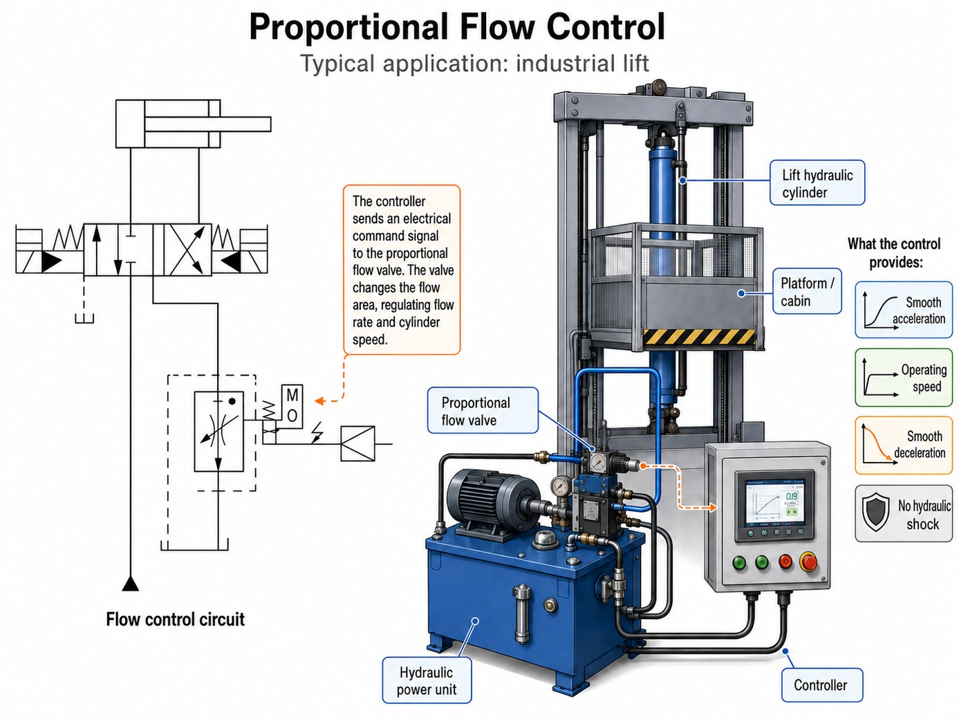
| Proportional flow valve | Oil flow | cylinder speed, hydraulic motor speed, smooth flow |
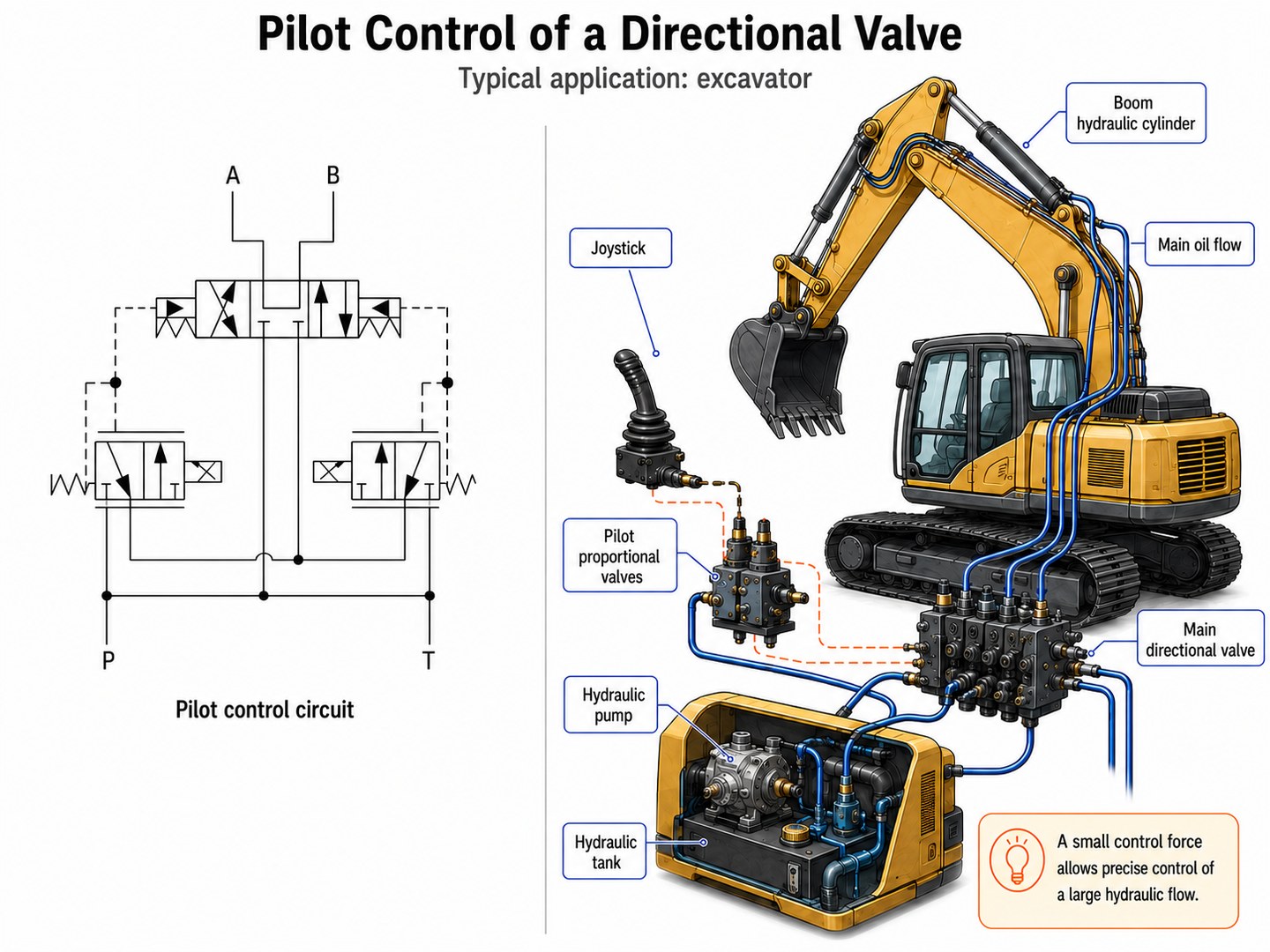
| Proportional directional valve | Flow direction and flow rate | cylinder movement forward/backward, lifting/lowering, positioning without servo precision |
| Proportional cartridge | Depends on the specific cartridge | mobile hydraulics, compact manifolds, special machinery |

More about valve mechanics: How a proportional hydraulic valve works.
2. Why an Amplifier Is Needed, Not Just a PWM Output
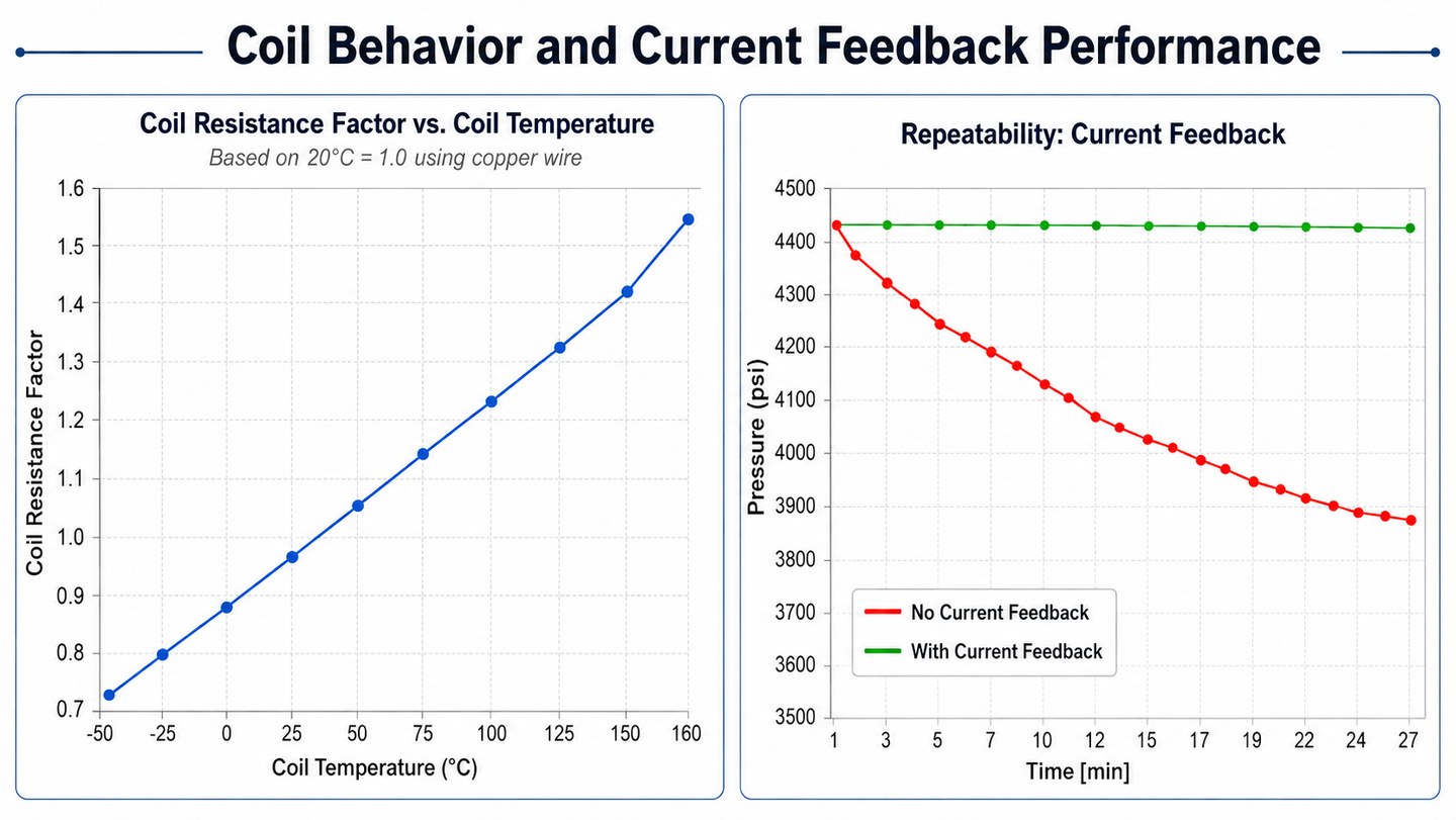
The solenoid coil is an inductive load. It has resistance, inductance and noticeable heating during operation. If voltage is applied directly, the current depends on coil resistance. And resistance changes with temperature.
For example, a cold coil can draw one current, and after heating it can draw another. At the same voltage the current drops, magnetic force drops and the valve operating point drifts slightly. For a regular on/off valve this is often not critical: the main thing is that it switches. For a proportional valve, this is already a problem because current is linked to valve position and hydraulic result.
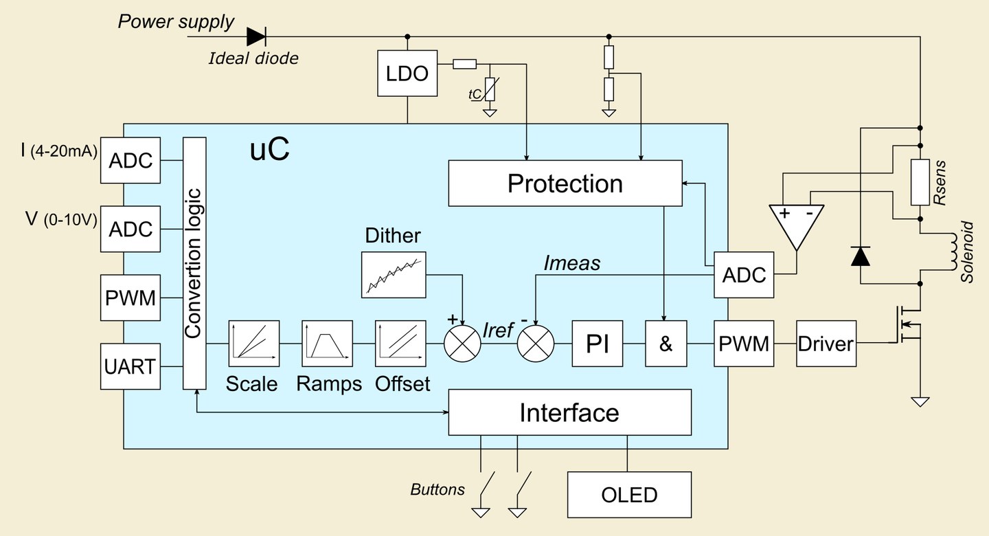
That is why a normal proportional valve amplifier works as a current regulator. It measures the actual coil current and controls the power switch so that the current follows the command.
A good amplifier solves several tasks at once:
- Stabilizes current so that valve behavior depends less on coil heating and supply sag.
- Limits maximum current so the coil is not overheated and the valve datasheet is not exceeded.
- Sets minimum working current to compensate for the valve deadband.
- Adds dither to reduce sticking and hysteresis.
- Generates ramp, meaning smooth current rise and fall, so the hydraulic system does not jerk.
- Monitors faults: short circuit, open coil, input overrange and supply problems.
More about current control: Why a proportional valve is controlled by current.
3. PWM and Dither Are Not the Same Thing
This is a common point of confusion.
Power-stage PWM is the way the driver controls the switch to produce the required average current through the coil. The frequency of this PWM is usually fairly high: kilohertz or tens of kilohertz. The coil smooths current because of its inductance, and the regulator selects the duty cycle to hold the required current.
Dither is a separate low-frequency modulation of the current setpoint. It is needed not for power conversion, but for the valve mechanics. A small current "shake" helps the spool or plunger avoid sticking in static friction, improves repeatability at small commands and reduces hysteresis.
In other words:
- PWM is "how the driver creates current";
- dither is "how the driver helps the valve mechanics move more smoothly and repeatably".
In practice, dither is tuned on the machine. Too little amplitude may have no effect. Too much amplitude can create vibration, noise and flow or pressure pulsation. Frequency also matters: too low is visible in the hydraulics, too high may have almost no mechanical effect.
Usually the starting point is moderate values, then the system behavior is observed. In VL-PVD1-24, dither is set by frequency and amplitude, and the modulation waveform is usually triangular.
More detail: PWM, dither and hysteresis in plain terms.
4. Imin, Imax, Deadband and Ramp
A proportional valve almost always has a range where a command is already present, but the valve does not yet produce a noticeable result. This may be caused by spool overlap, friction, spring force or valve design. That is why amplifiers often have an Imin setting: the minimum working current.
Imin helps the valve start from a clear point instead of after a long empty part of the command range. For example, a 0-10 V input can be configured so that at 2 V the output current immediately becomes 0.5 A, while below 2 V the current remains 0 A.
Imax is the maximum coil current. It is set according to the valve or coil datasheet, or according to the required operating mode. It is both scaling and protection against excessive current.
Ramp limits the rate of current change. It is needed so the hydraulic system does not react to a step command with a sharp impact.

Example setting:
- input signal: 0-10 V;
- working input range: 2-8 V;
- coil current: 0.5-2.0 A.
Then:
| Input | Coil current |
|---|---|
| 1 V | 0 A |
| 2 V | 0.5 A |
| 5 V | approximately 1.25 A |
| 8 V | 2.0 A |
| 10 V | 2.0 A |
More about tuning: Imin, Imax, deadband and ramp.
5. How to Know Whether an Amplifier Can Be Used as a Replacement
If an old Bosch Rexroth, Parker, HAWE, Wandfluh, Atos, Duplomatic or similar amplifier has failed, it is not always necessary to find the exact same module. In many cases it can be replaced with a modern universal driver if the key parameters match.
The important thing is to look not only at the old module brand, but at the actual task:
- Check the valve type: is it proportional?
- What maximum current does the coil need?
- Is there one solenoid or two A/B coils?
- What command signal comes from the controller: 4-20 mA, 0-10 V, PWM?
- Is there spool position feedback such as LVDT?
- Are dither, ramp and Imin/Imax needed?
- What enclosure and wiring are required?
One separate point is important: if the valve has LVDT or other spool position feedback, a regular coil driver may be insufficient. Such an application needs a controller that closes the position loop. The same applies to valves with electronics built directly into the valve: a command is sent to them, not coil current. In some cases that electronics can also be replaced, but this is a different task.
Detailed checklist: How to choose a replacement proportional valve amplifier.
6. VL-PVD1-24
VL-PVD1-24 is an electronic solenoid current driver for proportional hydraulic valves and directional valves without spool position feedback. It is designed to control one coil. For a directional valve with two A/B coils, two devices or a two-channel version are normally used.
The main idea of the device is to give an engineer a simple and flexible tool for controlling a proportional coil without developing custom electronics and without being tied to a module from a specific brand.
Main features:
- 12-30 V DC supply;
- 0-3.0 A coil current control;
- closed-loop current control;
- command inputs: 0-10 V, 4-20 mA/0-20 mA, PWM, UART;
- Imin/Imax setup;
- independent input and output scaling;
- ramp for current rise and fall;
- dither 10-300 Hz, 0-0.4 A peak-to-peak;
- 16 kHz power-stage PWM frequency;
- current regulator dynamics modes: FAST/NORM/SLOW;
- OLED display and two buttons for setup without a PC;
- UART 115200 8N1, PC utility and open exchange format;
- indication of short circuit, open coil, supply state and input overrange.
VL-PVD1-24 is well suited for applications where the coil must be controlled directly: proportional pressure valves, flow valves, cartridges, single-coil valves and directional valves when two channels are used.
It is not a servo amplifier and is not intended for valves where the amplifier itself must close the spool position loop. The device also has no boost converter: the maximum achievable current is limited by supply voltage, coil resistance and circuit losses. This is normal engineering practice, but it must be checked during selection.
Detailed device description: VL-PVD1-24 as a ready-made proportional valve driver.
Project: proportional hydraulic valve current controller.
Documentation: VL-PVD1-24 manual, PDF.
7. Conclusion
In a normal system, the amplifier should control current, account for the deadband, limit the maximum, add dither, generate smooth ramps and protect the power output.
If all of this is easy to configure, the valve is faster to commission, an old module is easier to replace, and the hydraulic system is easier to adapt to a specific machine. VL-PVD1-24 was designed for exactly these tasks: a compact current driver for proportional valves, with a normal set of engineering adjustments and straightforward wiring.
If you need to choose a driver for a specific valve or replace a failed amplifier, send the coil parameters, photos of the valve and the old module. We will help check compatibility and understand which wiring option is better.
Integration of the amplifier into your system is also an important point.
More detail: Wiring and installation of a proportional valve driver.
Sources and Materials Used for This Article
- HydraForce — Electro-Hydraulic Proportional Valves Course Manual Basic theory on proportional valves, PWM, dither, Imin/Imax, ramp, hysteresis and valve types.
- HydraForce — Solenoid Training Manual Theory on solenoids, coils, magnetic systems, plungers and coil designs.
- Bosch Rexroth — Proportional flow control valve Type 3(2)FREX, RE 29219 An industrial example of the chain: command, electronics, regulated PWM current, dither, proportional solenoid and spool.
- Texas Instruments — Current Controlled Driver for 24-V DC Solenoid With Plunger Fault Detection, TIDA-00289 Reference material on current-controlled solenoid drivers, PWM current control, peak/hold operation and plunger movement diagnostics.
- Texas Instruments — Automotive Proportional Solenoid Drive With Highly Accurate Current Sensor Reference material on proportional solenoid control and current measurement.
- Texas Instruments — Using Motor Drivers to Drive Solenoids Overview of solenoid drive circuits and power topologies.
- Parker — Series PWDXXA-40X Electronic for Proportional DC Valves An industrial amplifier example with MIN/MAX settings, dither, initial current, cable-break detection and software configuration.
- Bosch Rexroth — VT-SSPA1 plug-in proportional amplifier An example of a plug-in amplifier with ramp, bias/current settings and dither.
- Wandfluh — proportional amplifiers and electronics Examples of industrial amplifiers with dither, ramp and current settings.
- Atos — proportional valve electronics Examples of separating valves without sensors from feedback valves, as well as off-board electronics.
- Machinery Lubrication — Hydraulic Proportional Valves Material on open-loop, closed-loop and LVDT valves.
- Atos — Electrohydraulic proportional controls, F001 Open-loop and closed-loop motion-control diagrams for electrohydraulic axes.