What VL-PVD1-24 Is Designed For
VL-PVD1-24 is an electronic solenoid current driver for controlling proportional hydraulic valves and directional valves without spool position feedback.
It is suitable for applications where the coil has to be driven directly:
- proportional pressure valves;
- proportional flow valves;
- electro-proportional cartridge valves;
- single-coil valves;
- proportional directional valves when two devices or a two-channel version are used;
- replacement of many single-channel amplifiers when current, supply, input and wiring match.
The main idea is to make proportional valve tuning a normal engineering procedure, not a matter of selecting resistors, adjusting potentiometers and "turning this screw a little".
Device documentation: VL-PVD1-24 manual, PDF.
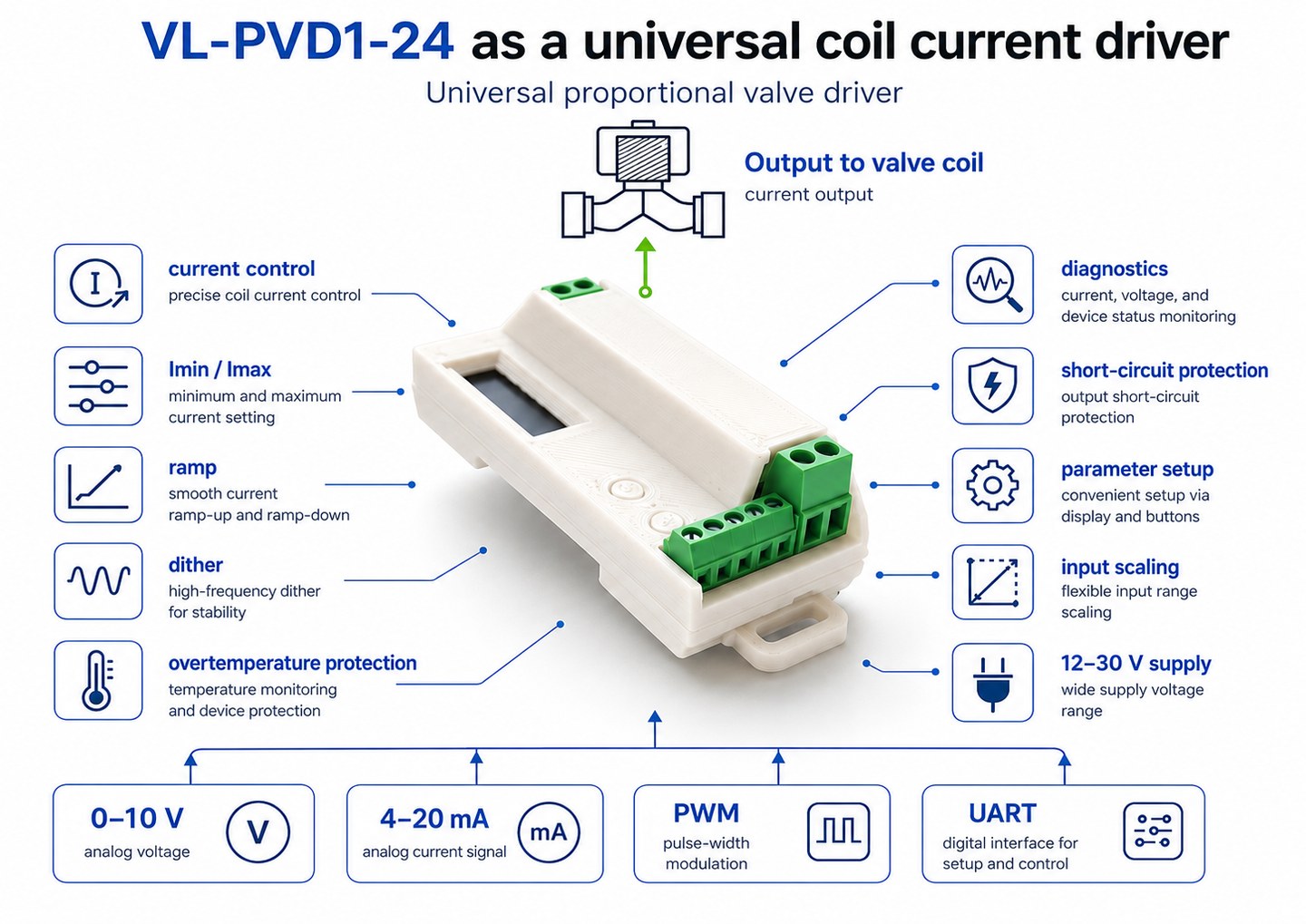
What It Does
The device accepts a command from an external system and converts it into regulated coil current.
The command can be:
- 0-10 V voltage;
- 4-20 mA or 0-20 mA current signal;
- PWM signal;
- UART command.
Inside the device, input boundaries, output current boundaries, ramp, dither and regulator mode are configured. At the output, the coil current is controlled in a closed loop.
Main Specifications
| Parameter | Value |
|---|---|
| Supply | 12-30 V DC |
| Absolute maximum input supply | 35 V |
| Output current | 0-3.0 A, configurable |
| Control type | closed-loop current control |
| Power topology | low-side N-MOSFET, coil connected to +V |
| Power-stage PWM frequency | 16 kHz |
| 0-10 V input | configurable boundaries, overrange warning |
| 4-20 mA / 0-20 mA input | configurable boundaries |
| PWM command input | 1-20 kHz, 0-100%, 8-15 V levels |
| Dither | 10-300 Hz, 0-0.4 A peak-to-peak, triangular waveform |
| Ramp | separate rise/fall settings, 0-10000 ms |
| Regulator modes | FAST / NORM / SLOW |
| Interfaces | OLED + 2 buttons, UART 115200 8N1, PC utility |
| Mounting | DIN rail |
| Dimensions | 36 × 88 × 24 mm |
Input and Output Scaling
One of the useful features of the device is flexible scaling. You can independently set:
- lower and upper boundaries of the input signal;
- minimum and maximum output current;
- working range for a specific coil.
This allows the driver to adapt to different systems:
- 0-10 V;
- 2-8 V;
- 4-20 mA;
- 0-20 mA;
- PWM 10-90%;
- limited coil current, for example 0.4-1.6 A.
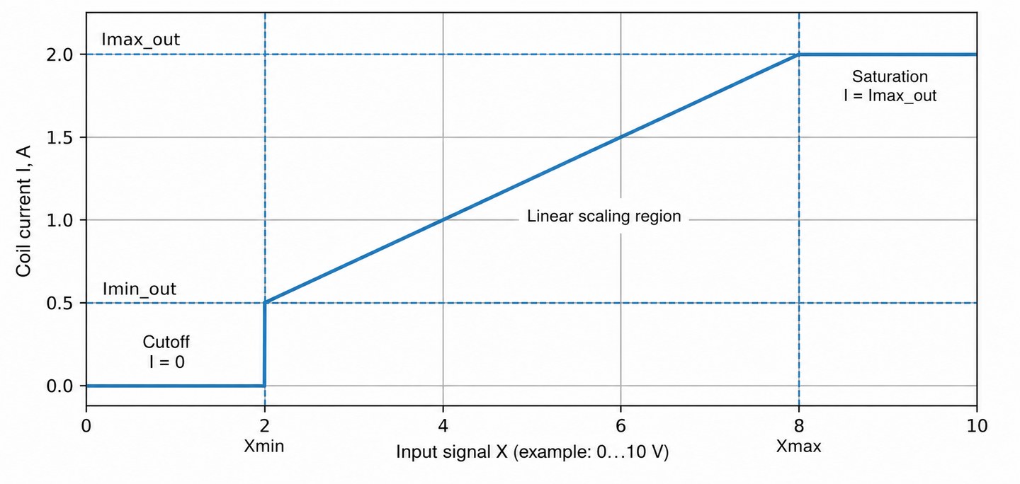
Example:
- input from PLC: 2-8 V;
- the valve starts working at about 0.45 A;
- maximum coil current is 1.6 A.
Configure:
Vmin = 2.00 V
Vmax = 8.00 V
Imin = 0.45 A
Imax = 1.60 A
Now everything below 2 V is treated as zero command. From 2 to 8 V, current rises from 0.45 to 1.60 A. Above 8 V, current is limited at 1.60 A.
Dither in VL-PVD1-24
Dither is set by two parameters:
- frequency: 10-300 Hz;
- amplitude: 0-0.4 A peak-to-peak.
The waveform is triangular. At zero amplitude, dither is disabled.
Why it is needed:
- reduce spool sticking;
- improve repeatability at small commands;
- reduce the effect of static friction;
- make the valve more predictable near the start of opening.
The device automatically limits dither near the current boundaries. This helps avoid modulation clipping when the average current is close to 0 A or to the upper limit.
Ramp Up and Ramp Down
VL-PVD1-24 provides separate settings for current rise time and current fall time. This is convenient because real hydraulic systems often need to open the valve at one rate and close it at another.
For example:
- smooth pressure rise over 300 ms;
- faster pressure release over 100 ms;
- or the opposite: fast rise, but soft closing.
FAST / NORM / SLOW Regulator Modes
Different coils behave differently. Long cables, high inductance, interference and valve details all affect current-loop stability.
That is why the device has three dynamic modes:
- NORM: default mode, a good starting point for most tasks;
- FAST: when fast current response is needed;
- SLOW: when stability and soft behavior matter more, for example with a "heavy" coil or long cable.
Setup Without a PC and With a PC
The device can be configured directly on site through the OLED display and two buttons. This is useful during service work: a laptop, adapter and time are not always available.
For more convenient work, UART and a PC utility are available. They allow parameters to be changed faster, profiles to be used, setup to be automated and the open exchange format to be used.
Diagnostics and Protection
VL-PVD1-24 shows important states:
- output short circuit;
- open coil;
- low supply voltage;
- high supply voltage;
- input voltage overrange;
- input current overrange.
In case of a short circuit or supply overvoltage, the output is disabled. For warnings, the device reports the condition so the service engineer sees the problem instead of guessing from valve behavior.
Where VL-PVD1-24 Can Replace an Old Amplifier
The device can be considered as a functional alternative for many single-channel proportional valve amplifiers if the key parameters match:
- the coil is driven directly;
- no mandatory LVDT loop is closed in the amplifier;
- coil current is not above 3 A;
- supply voltage is in the 12-30 V range;
- the command signal is compatible: 0-10 V, 4-20 mA/0-20 mA, PWM or UART;
- Imin/Imax, dither and ramp settings are required.
These may be systems that previously used single-channel plug-in, DIN-rail, panel-mount or simple electronic modules for proportional coils.
What Is Not the Target Application
The important limitations are:
- this is not a servo amplifier;
- this is not an LVDT spool-position controller;
- this is not a driver for a valve with built-in electronics that already accepts a ready command;
- a directional valve with two coils needs a second channel, meaning a second amplifier or a two-channel version.
Quick Commissioning
A typical startup order:
- Connect supply, coil and command input.
- Select command source: VOLT, CURR, PWM or UART.
- Set Imax according to the coil datasheet.
- Set Imin if the deadband has to be removed.
- Set input boundaries.
- Set ramp for current rise and fall.
- Enable dither if needed.
- Check operation at small, medium and maximum command.
- Save settings.
What to Send if You Need Help with Selection
To check compatibility, send:
- a photo of the valve;
- a photo of the coil marking;
- a photo of the old amplifier, if available;
- wiring diagram or terminal photo;
- supply voltage;
- input signal type;
- required coil current or the valve datasheet.
With this data, it is usually possible to understand quickly whether VL-PVD1-24 fits, whether two channels are needed, whether input-signal conversion is required or whether another option should be chosen.