Skip to content
Proportional hydraulic valve driver board

Projects / Industrial automation and embedded control
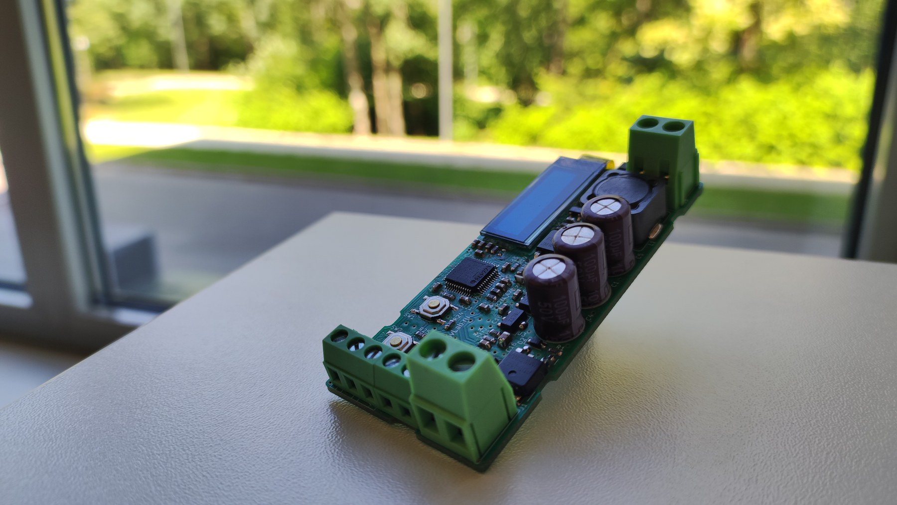
Proportional hydraulic valve current controller

Compact industrial current controller for proportional hydraulic valves: 12...30 V DC supply, 0...3 A coil-current regulation, 0...10 V / 4...20 mA / PWM / UART setpoints, ramp modes, dither and diagnostics.

Task

What had to be solved

The task was to make a specialized power interface between an automation system and a proportional hydraulic valve, where the controlled variable is coil current rather than a simple applied voltage.

Result

What the project reached

The module solves a practical industrial-control task: it regulates valve-coil current repeatably, protects the output and provides clear setup for a specific valve or distributor.

Proportional hydraulic valve driver board
Proportional hydraulic valve driver board during debugging

Project materials

Photos and working materials

Proportional hydraulic valve driver during thermal check
Proportional hydraulic valve drivers in enclosures, external view

Documentation

Device manual

Engineering context

Important constraints

The target devices are proportional valves and distributors without spool-position feedback.

The solenoid force is related to current, while current depends on coil resistance, inductance, temperature and supply voltage.

Smooth transitions are needed to reduce hydraulic jerks and sharp transients.

The device has to be configurable for 0...10 V, 4...20 mA, PWM and UART control inputs.

Work done

What was included

Current-controller circuitry for a proportional valve coil.

Firmware with PI current regulation, ramp functions and dither.

Support for 0...10 V, 4...20 mA, PWM and UART setpoint inputs.

Local setup with an OLED display and buttons.

Parameter storage and fault diagnostics.

Manual and interface-accessible settings for current limits, ramp timing, dither and regulator mode.

Details

Engineering project description

Operating principle

The controller measures current through the solenoid coil and closes an internal regulation loop around this measured current. The user sets output-current limits and input-signal scaling, so an allowed input signal can be mapped to the required output current.

Separate rise and fall times allow the setpoint to change with a configured speed instead of a hard step. In hydraulics this helps reduce jerks and overshoot.

Main capabilities

  • closed-loop coil-current regulation in the 0...3.0 A range
  • 12...30 V DC supply for 24 V systems
  • 0...10 V, 4...20 mA, PWM and UART setpoint inputs
  • independent minimum and maximum input-signal settings
  • independent minimum and maximum output-current settings
  • separate current rise-time and fall-time settings
  • FAST, NORM and SLOW PI-regulator modes
  • dither frequency and amplitude settings
  • local setup with OLED display and two buttons
  • parameter storage in non-volatile memory

Technical parameters

  • nominal system: 24 V
  • absolute supply maximum: 35 V
  • output topology: low-side N-MOSFET switch
  • maximum continuous current: 3 A at +25 C
  • current-regulation accuracy: +/-1% of range
  • power PWM frequency options: 2 / 4 / 8 / 16 kHz, with 16 kHz as default
  • rise and fall time: 0...10000 ms
  • dither frequency: 10...300 Hz
  • dither amplitude: 0...0.4 A pk-pk
  • UART service interface: 115200, 8N1
  • DIN-rail mounting

Diagnostics and protection

  • overvoltage and undervoltage supply monitoring
  • input-voltage and current-setpoint limit checks
  • short-circuit protection with output shutdown
  • open-coil indication

Contact

Discuss your engineering task

Contact us by email. We discuss custom electronics and automation tasks remotely with companies, labs, small businesses and individual customers worldwide.