Why Wiring Matters
Even a good driver can be compromised by poor wiring. A proportional valve is a power inductive load, and nearby there are often pumps, motors, VFDs, relays, long cables and shared grounds. Wiring affects not only reliability, but also control accuracy.
A typical task is: 24 V supply, a coil on the valve, a command signal from a PLC or panel, and setup through buttons or a PC.
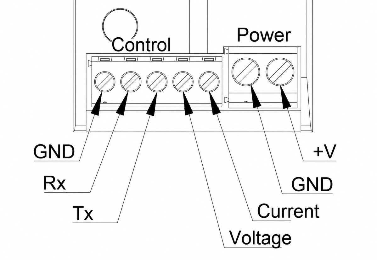
Power Supply
The driver supply must match the operating range of the device and the coil-current task. For VL-PVD1-24, the working supply range is 12-30 V DC.
Important points:
- the supply must be able to provide the coil current;
- supply sag can limit achievable current;
- long wires create voltage drop;
- local power decoupling near the device is useful;
- the supply negative must be connected reliably and with an adequate wire cross-section.
Ground and Common Wire
In many compact drivers, power ground and signal ground are connected internally. This is convenient, but it requires proper routing. If the supply negative is poor, part of the load current can try to return through signal ground. This is a bad scenario: measurement errors, interference, overheated PCB traces or damaged signal circuits.
Practical rule: the power negative must be reliable. Signal ground must not become the power return path.
Cable to the Coil
The coil is a power inductive load. Its wires should preferably be routed as a pair, close to each other or as a twisted pair. This reduces current-loop area and interference.
Do not route the coil cable together with motor cables, VFD cables or high-power lines. If cable routes cross, it is better to cross at an angle rather than run them in parallel.
Do Not Add Your Own Diodes or Capacitors at the Coil
This is important. If the driver already has its own demagnetization and current-measurement circuit, an external diode, capacitor or RC network on the coil can disturb regulator operation, change current decay, distort diagnostics or increase interference.
So additional components should not be added to the coil output unless the driver manufacturer explicitly allows it.
0-10 V Input
The 0-10 V analog input is simple and common, but it is more sensitive to interference than a current loop. It is best used over short distances or with shielded twisted pair.
The signal wire should be routed together with its GND. The shield is usually connected at one side only: at the signal source or in the cabinet, depending on the grounding system.
4-20 mA Input
A current input is usually better for long lines and noisy environments. That is why 4-20 mA is so common in industry. Even if there is voltage drop along the cable, loop current is maintained as long as the source has enough compliance voltage.
For amplifier replacement this is convenient: if the old module accepted 4-20 mA, a new driver with a current input can often be configured for the same range. If the source outputs 0-20 mA, that is also often solved by input boundary settings.
PWM Input as a Command
A PWM command input is not the same thing as power PWM on the coil. The external controller can transmit a command through duty cycle, and the driver then converts it into a current setpoint and controls the power transistor by itself.
For example, 0% may correspond to 0 A, 100% to Imax, and the current is scaled linearly between them. PWMmin/PWMmax input boundaries allow the range to be adjusted.
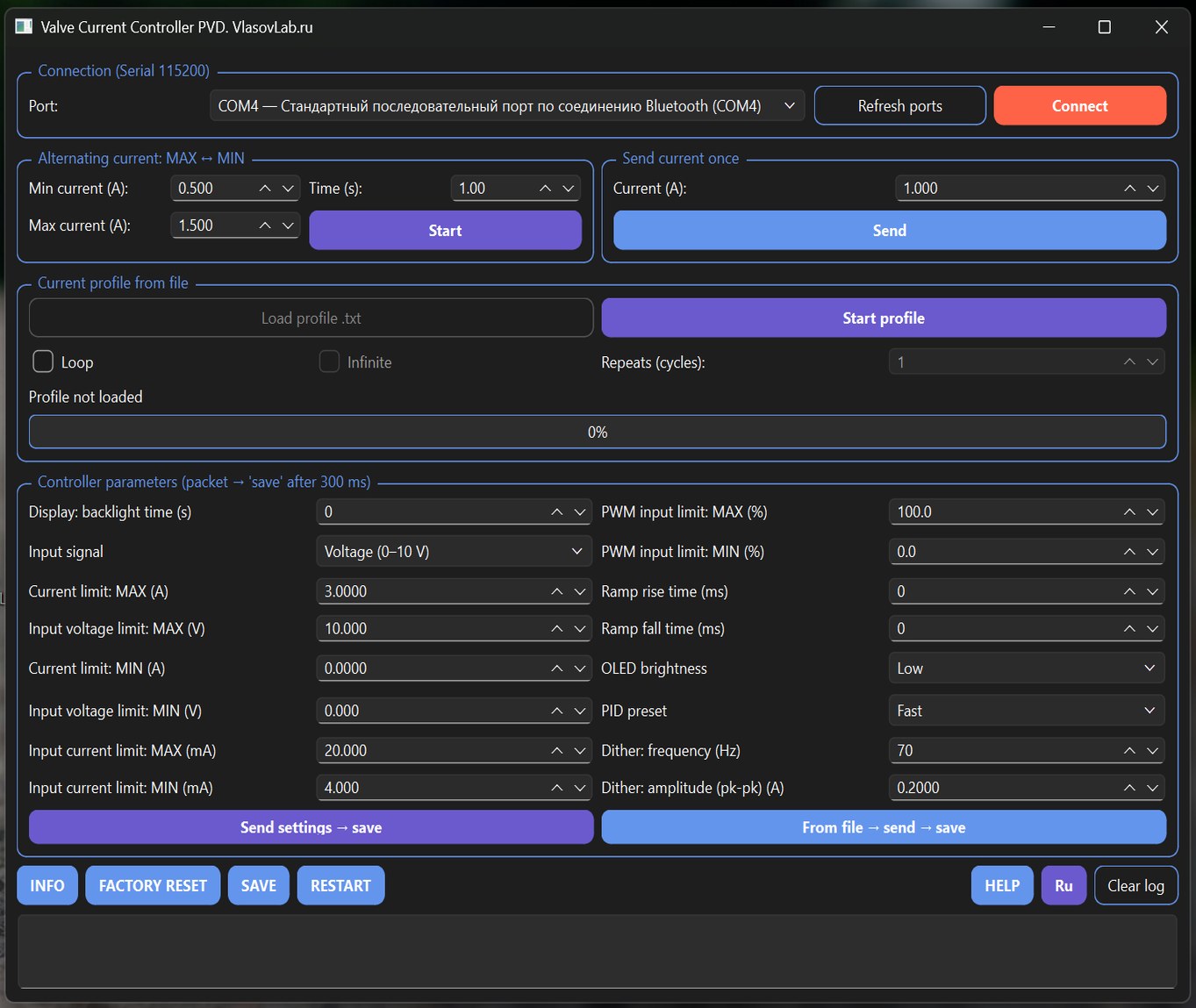
UART and PC Setup
UART is useful for setup, diagnostics and automation. But when connecting to a PC, remember common ground and the absence of galvanic isolation unless the device provides it. For debugging in a real hydraulic system, a USB isolator is useful.
Through a PC, it is faster to change parameters, save profiles, set test modes and repeat settings on multiple devices.
Common Wiring Mistakes
| Mistake | Possible result |
|---|---|
| Thin or poor supply negative wire | current errors, heating, signal-ground damage |
| Coil cable routed next to a VFD | interference, faults, noise |
| External diode on the coil | incorrect current decay, disturbed driver operation |
| Long 0-10 V line without shield | floating command, valve jitter |
| 4-20 mA and 0-10 V mixed up | wrong input mode, no control |
| Two coils connected to one channel | overload or incorrect control |
| UART connected directly to a PC in a noisy system | ground-loop risk, communication faults, adapter damage |
Practical Conclusion
Wiring a proportional valve driver is not complicated magic, but several rules should not be ignored: proper supply, reliable GND, careful coil cable routing, correct input selection and no unnecessary components on the output.
When everything is connected correctly, valve tuning becomes predictable, and problems are easier to find by parameters rather than by random interference.