The Main Point
In most practical cases, a proportional valve is controlled by coil current, not by the voltage on the coil.
Voltage is a way to make current flow. But the valve itself does not "feel" voltage. It responds to magnetic force, and magnetic force depends on current, the geometry of the magnetic system and the armature position.
In simplified form:
more current -> more magnetic force -> more action on the valve.
That is why a good amplifier should not merely output PWM. It should measure current and regulate it.
The Coil Is Not Just a Resistor
If the solenoid coil were an ordinary resistor, everything would be simpler: apply voltage and get current according to Ohm's law. In that case, the current would settle almost immediately at:
I ≈ U / Rwhere U is the applied voltage and R is the active resistance of the load.
But a solenoid coil is not only wire resistance. Electrically it is an R-L load: the active winding resistance Rcoil in series with the coil inductance Lcoil.
Resistance defines the steady-state current. If DC voltage is applied to the coil and enough time passes, the current approaches:
Isteady ≈ U / RcoilThis value is often used for a rough estimate: for example, if a 24 V coil has a resistance of 12 ohms, its steady-state current will be about 2 A.
Inductance changes how the coil behaves over time. It resists fast changes in current. So the current through the coil cannot instantly become 2 A after power is applied, and it cannot instantly fall to zero after power is removed.
When voltage is applied, current rises smoothly along an exponential curve:
i(t) = (U / R) · (1 − e^(−t/τ))where τ is the time constant of the R-L circuit:
τ = L / RThe larger the coil inductance L, the more slowly current changes. The larger the active resistance R, the faster current reaches its steady-state value.
After one time constant τ, current reaches about 63% of the steady-state value. After three time constants it reaches about 95%. After five time constants, current can be treated as practically settled.
For example, if the coil has:
L = 20 mH
R = 12 ohm
then the time constant is:
τ = L / R = 0.02 / 12 ≈ 0.0017 s ≈ 1.7 msThis means the current does not appear instantly. It rises over several milliseconds.
When the coil is switched off, the situation is also different from an ordinary resistor. Energy is stored in the magnetic field of the coil:
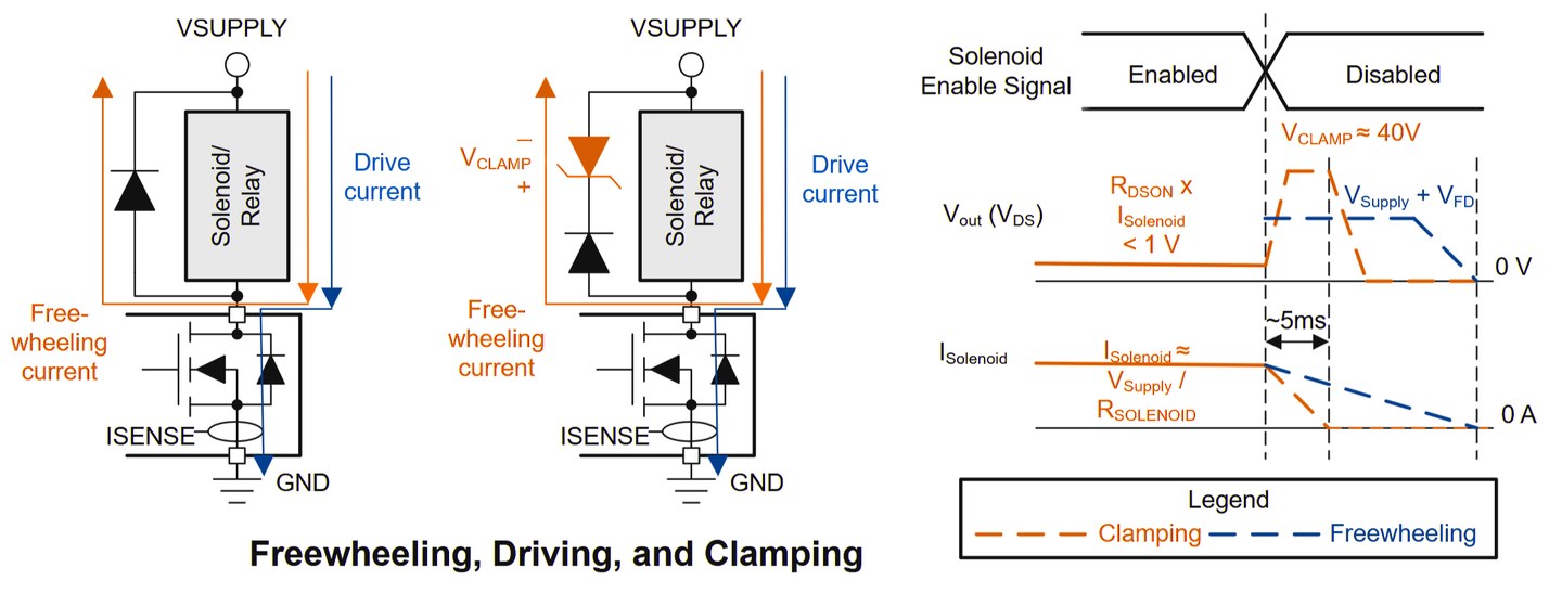
E = 1/2 · L · I²This energy cannot disappear instantly. After the switch turns off, the coil tries to keep the previous current flowing and creates a voltage with the polarity needed to maintain that current. If the current has a path through a diode, TVS, snubber or another protective element, it decays gradually.
In the simplest form, current decay can be described by an exponential curve:
i(t) = I0 · e^(−t/τ)where I0 is the current at the moment of switch-off.
In practice, the speed of current decay after switch-off depends not only on the coil itself, but also on the power stage. For example, if a regular Schottky diode or fast diode is placed across the coil, current decays relatively slowly because the demagnetization voltage on the coil is low. If a higher clamp voltage is used, such as a TVS, Zener chain or active fast-decay mode, current can fall much faster.
For a proportional valve, this matters for two reasons.
First, coil current is related to magnetic force, and magnetic force affects the position of the plunger or spool. If current changes slowly, the valve cannot instantly move to a new position either.
Second, when PWM control is used, the power switch constantly applies and removes voltage from the coil. But because of inductance, the coil current does not follow the PWM voltage waveform. The voltage on the switch and coil may be rectangular, while the current remains smoothed. This is why the solenoid coil itself partly works as an electrical filter.
This is useful: the power stage can switch voltage quickly, while the coil current becomes much smoother. But this alone is not enough. A proportional valve needs controlled current, not just average voltage. A proper coil driver therefore measures the actual current and adjusts PWM so that the requested current is maintained despite coil resistance, temperature, supply voltage and load dynamics.
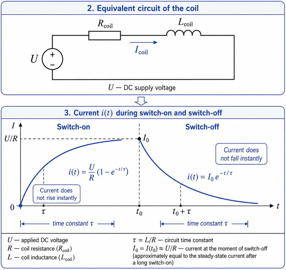
[Equivalent coil circuit: active resistance Rcoil in series with inductance Lcoil. The graph shows that when voltage is applied, current does not rise as a step, but follows an exponential curve. When the voltage is removed, current also does not disappear instantly; it decays smoothly while the energy stored in the magnetic field is dissipated in the power circuit.]
Coil Heating Changes Resistance
The coil heats up during operation. The resistance of the copper winding increases with temperature. If voltage supply stays the same, current decreases.
For an on/off valve this is often acceptable: the valve has already switched and is held. For a proportional valve it is worse, because a change in current changes magnetic force and the operating point.
The logic is simple:
- cold coil: lower resistance, higher current;
- hot coil: higher resistance, lower current;
- at the same voltage, solenoid force can change.
A closed-loop current amplifier compensates for this: it increases or decreases the PWM duty cycle so that the current remains at the requested value.
How Closed-Loop Current Control Works
In a simple version, the power stage of the driver is arranged as a low-side switch:
- the coil is connected to the positive supply;
- the second coil terminal goes to the power MOSFET;
- the MOSFET switches the coil to ground;
- current is measured by a shunt or current sensor;
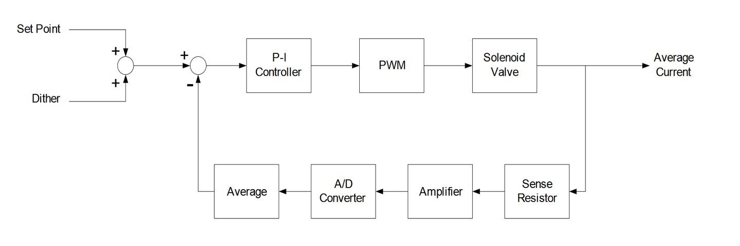
- the microcontroller compares measured current with the setpoint;
- the regulator changes PWM so that the error becomes smaller.
This is closed-loop current control.
The main idea is that the driver does not just apply some voltage to the coil or output a fixed PWM value. It continuously measures actual coil current and compares it with the requested value Iset.
If measured current Imeas is below the setpoint, the regulator increases PWM duty cycle. The MOSFET stays on longer, supply voltage is applied to the coil for more time, and current rises faster.
If measured current is above the setpoint, the regulator reduces PWM duty cycle. The average voltage on the coil decreases, and the current falls or rises more slowly.
The difference between setpoint and measured current is the control error:
e = Iset − ImeasA PI or PID regulator processes this error and generates the control signal for PWM. As a result, the loop automatically adjusts the power stage so that the actual coil current stays close to the setpoint.
This approach is especially important for proportional valves. Coil resistance changes with heating, supply voltage can sag, and the coil itself is an inductive load. Without feedback, the same PWM value does not always produce the same current.
The closed loop solves this: the driver controls not a "PWM percentage", but the actual coil current. The valve therefore receives a more stable magnetic force, and its behavior becomes more repeatable and predictable.
Why a PLC PWM Output Is Not Enough by Itself
Sometimes it looks tempting: "my PLC can output PWM, so I will connect the coil through a switch and that is it". For a simple on/off solenoid this may work. For a proportional valve, not always.
The problems are:
- No current measurement, so no compensation for heating and coil variation.
- No maximum current limit, so the coil can overheat.
- No proper Imin/Imax setup, so it is hard to remove the deadband.
- No independent dither, so the valve can stick at small commands.
- No ramp, so the hydraulic system can jerk.
- No diagnostics, so an open coil or short circuit becomes an unpleasant surprise.
Supply Voltage and Coil Resistance Limitations
A current driver is not magic. To reach the required current, it must have enough supply voltage.
A rough estimate of achievable current is:
Iachievable ≈ (Usupply - Ulosses) / Rcoilwhere:
Usupplyis the actual supply voltage;Ulossesis the voltage drop on the switch, shunt, wires and internal elements;Rcoilis the coil resistance.
Example: 18 ohm coil, 24 V supply, losses conditionally 1 V.
Iachievable ≈ (24 - 1) / 18 ≈ 1.28 AIf the setpoint is 2 A, it will not be physically reached. Not because the driver is "bad", but because the supply voltage is insufficient for that coil.
What Happens When the Switch Turns Off
The coil does not like abrupt current interruption. The energy stored in the inductance has to go somewhere. That is why the driver has a demagnetization path: a freewheel diode, TVS, active clamp or another circuit.
The demagnetization method affects:
- current decay speed;
- electromagnetic interference;
- voltage spikes;
- component heating;
- valve closing dynamics.
A freewheel diode usually gives soft and noise-resistant behavior, but current decay is not the fastest. Harder clamp circuits can speed up decay, but they require careful design and produce higher voltage on the switch.