Why a Proportional Valve Is Needed at All
In hydraulics, motion often has to be controlled, not just switched on and off. For example:
- lift a platform smoothly;
- limit cylinder speed;
- change clamping pressure;
- control a hydraulic motor;
- make braking softer;
- remove the impact at the end of travel;
- give the operator a normal smooth control instead of only two speeds.
Proportional valves and directional valves are used for these tasks. They provide intermediate states between "closed" and "fully open".
From the outside, such a valve can look almost like a regular solenoid valve: body, coil, connector. Inside, however, it is designed to work in intermediate positions. That is the main difference.

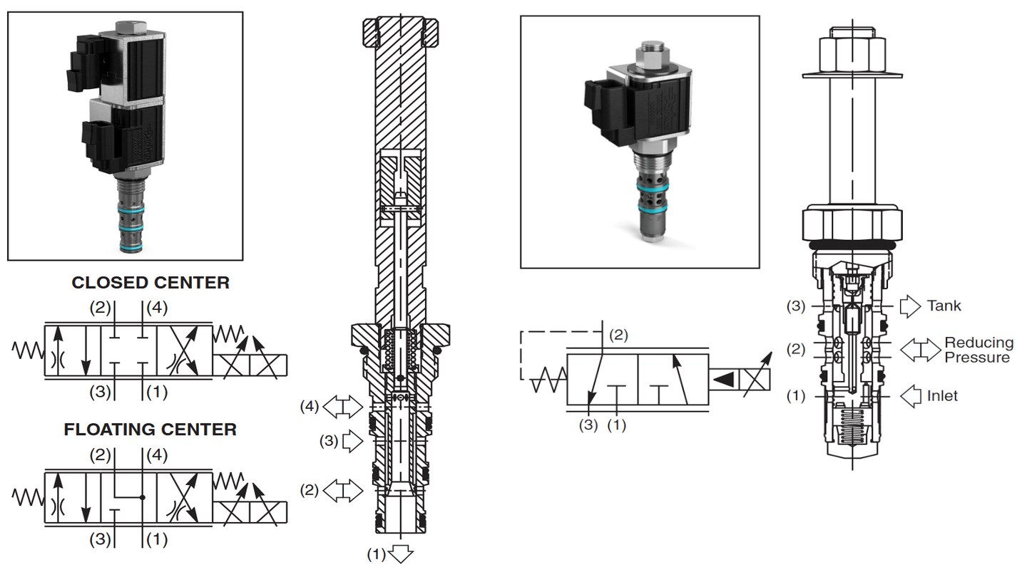
What the Valve Consists Of
In simplified form, a proportional valve has several important parts.
Solenoid coil. Current flows through it. The higher the current, the stronger the magnetic field.
Magnetic system. This includes the core, magnetic circuit, pole piece, armature or plunger. It turns coil current into mechanical force.
Spring. It returns the valve to its initial position and defines part of the mechanical characteristic.
Spool, plunger or valve element. This is the part that actually opens or closes the oil passage.
Hydraulic section. Channels, edges, seat, metering windows and compensation elements. This is where current is ultimately converted into flow, pressure or flow direction.
A proportional valve should not be treated as an ideal small electric motor where current directly defines position. In a real valve, current defines force, and position is the result of a force balance: magnetic force, spring force, hydraulic forces and friction.
Current -> Force -> Position -> Flow
The typical chain is:
- The amplifier supplies current to the coil.
- The coil creates a magnetic field.
- The magnetic system pulls the armature or plunger.
- The plunger acts on the spool or valve element.
- The flow area changes.
- Flow, pressure or flow direction changes.
In flow control valves this usually looks like a change in the metering window. In pressure valves, it is a change in force on the control element. In directional valves, it is the displacement of the spool relative to the working edges.
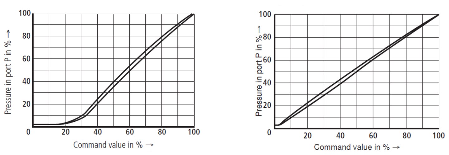
Why the Characteristic Is Not Ideal
Diagrams often show a clean straight line: current rises, flow rises. Real behavior has details.
First, the valve has a response threshold. At low current, the magnetic force may not be enough to overcome the spring, friction and spool overlap.
Second, there is hysteresis. If the current is increased and then decreased, the valve may not follow the same curve in both directions. The causes include friction, oil viscosity, magnetic hysteresis and mechanical design.
Third, there are tolerances and temperature. Oil viscosity, coil resistance and the mechanical condition of the valve all affect behavior.
That is why the amplifier should provide not just a "PWM percentage", but properly controlled current with settings for a specific valve.
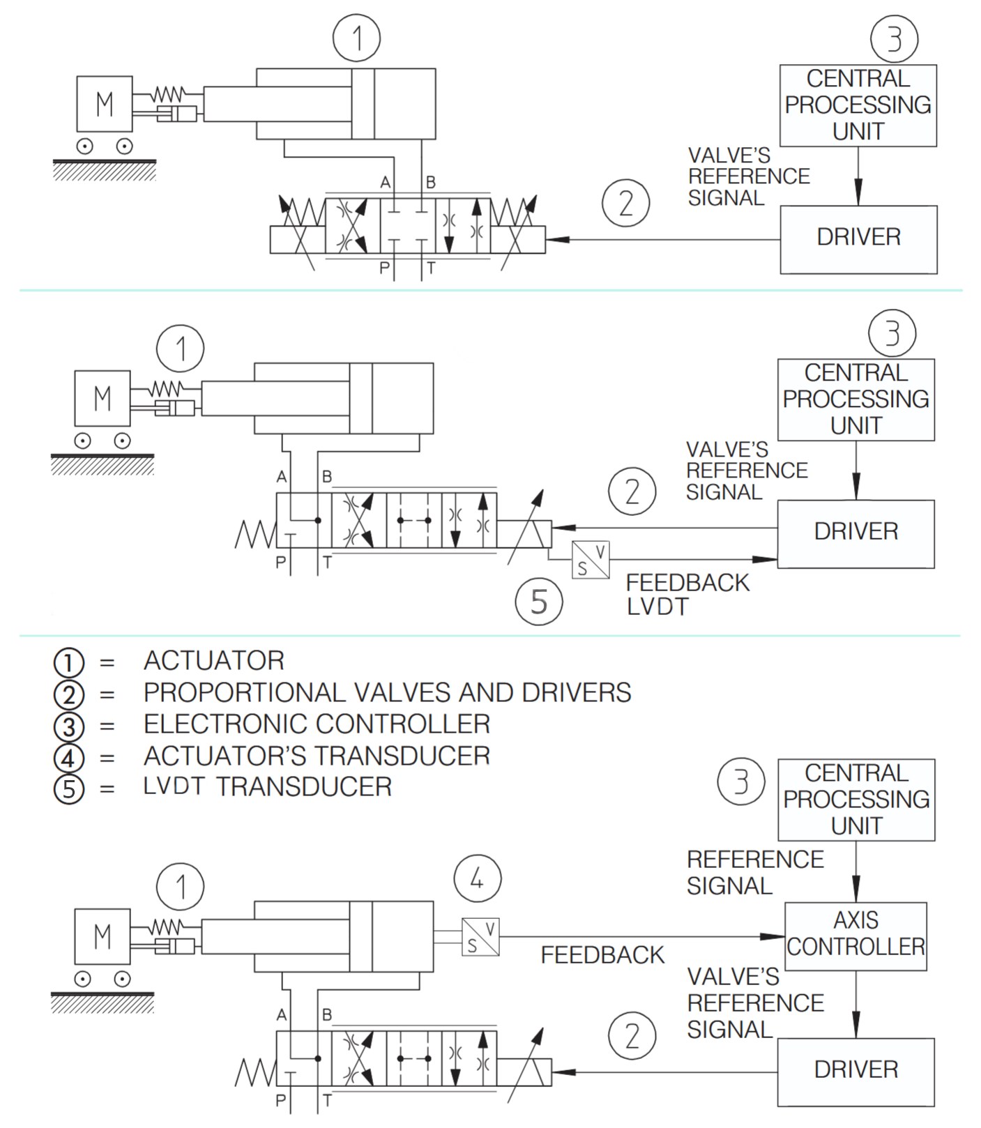
Open-Loop, LVDT and External Feedback
It is important not to mix several different feedback loops.
1. Coil current loop. Even a simple proportional valve driver usually works in closed-loop current control: it measures the actual coil current and changes the power-stage PWM so that the current follows the command. VL-PVD1-24 belongs to this class of devices: it controls coil current.
2. Valve without spool position feedback. In this kind of valve, the driver sets coil current, and the spool or plunger position comes from the balance of magnetic force, spring force, hydraulic forces and friction. This is often called an open-loop proportional valve. Many simple proportional pressure valves, flow valves and some directional valves work this way.
3. Valve with spool position feedback. More complex valves include an LVDT, inductive sensor or another spool position sensor. The electronics compares the command with the actual spool position and closes the loop specifically around spool position. Such a valve needs more than a coil driver: it needs an amplifier or controller that can work with the position sensor.
4. External machine motion loop. A separate case is when feedback is not on the valve spool, but on the actuator: cylinder, hydraulic motor, pressure or force. For example, a PLC or axis controller reads a cylinder position sensor and changes the valve command. In that system, the valve itself can still be open-loop by spool position, while the whole axis works in closed loop by cylinder position.
So the phrase "valve without feedback" has to be understood precisely: without spool position feedback inside the valve or its amplifier. It can still be used in a system where an external controller closes the loop by position, speed, pressure or force.
One Coil and Two Coils
Single-coil valves are often used for pressure or flow control. The rule is simple: one driver for one coil.
Proportional directional valves often have two coils: A and B. One shifts the spool in one direction, the other shifts it in the opposite direction. In that case, a two-channel amplifier or two single-channel drivers are needed.
Where This Is Used
Typical applications:
| Area | What is controlled |
|---|---|
| Hydraulic lifts and elevators | lifting/lowering speed, soft braking, pressure |
| Presses and clamps | force, pressure, smooth approach |
| Hydraulic power units | line pressure, flow to actuators |
| Test benches | controlled load, pressure, flow |
| Mobile machinery | boom, bucket and stabilizer movement, steering or auxiliary control |
| Production equipment | smoothness, repeatability, speed control |
Practical Conclusion
A proportional valve is a mechanical-hydraulic device controlled by coil current. The more accurately and conveniently the current is controlled, the easier the whole system is to set up.
So when choosing an amplifier, it is not enough to check only "24 V" and "the connector fits". You need to look at coil current, command signal type, dither, Imin/Imax, ramp and feedback limitations.