Skip to content
Two-channel high-voltage signal source, 20 kV and up to 1 kHz

Projects / Laboratory and scientific instruments
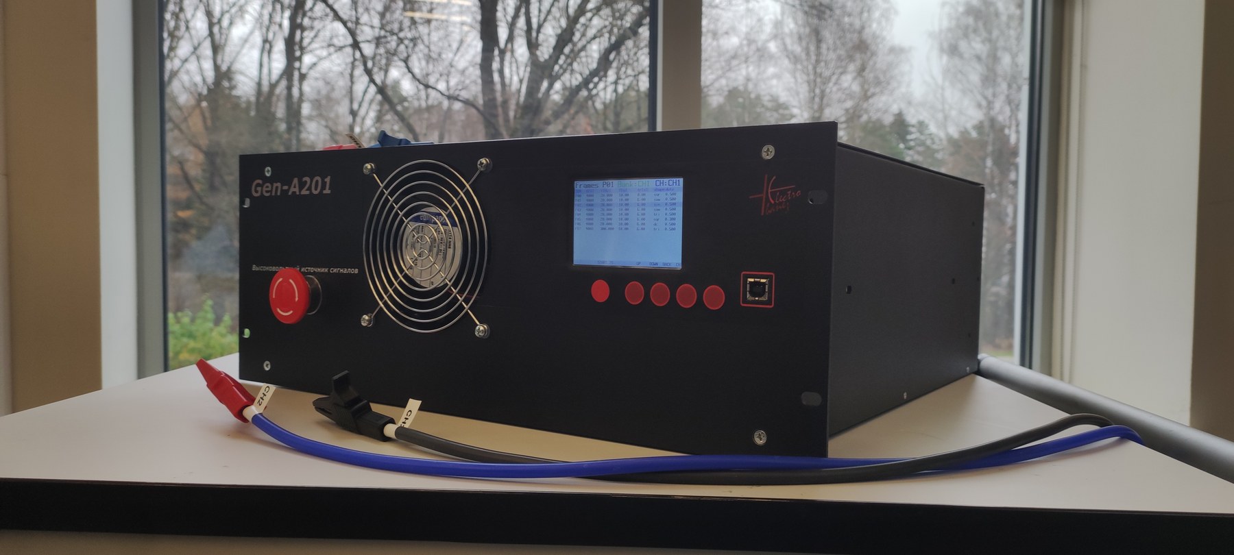
Gen-A201 two-channel high-voltage generator

Programmable two-channel high-voltage generator up to 20 kV for R&D tests: signal profiles, local HMI, PC utility and safety logic.

Task

What had to be solved

The task was to create a laboratory instrument for repeatable multi-step tests of dielectric materials and experimental samples with controlled high-voltage waveforms.

Result

What the project reached

A complete R&D instrument was developed: high-voltage hardware, embedded firmware, local operator interface, USB profile loading, PC utility, test profiles and safety logic.

Two-channel high-voltage signal source, 20 kV and up to 1 kHz
Two-channel high-voltage signal source, rear view

Project materials

Photos and working materials

Two-channel high-voltage signal source interface
Two-channel high-voltage signal source during testing on a sample

Documentation

Device manual

Engineering context

Important constraints

The device works with dangerous high voltage and therefore needed predictable safety behavior, interlocks and fault handling.

Two independent high-voltage channels had to run repeatable test scenarios.

The laboratory workflow required stored profiles, not only manual voltage adjustment.

The instrument had to work from its own local interface without permanent connection to a PC.

The expected loads were dielectric and capacitive samples typical for material and actuator-structure research.

Work done

What was included

Complete circuit design for the instrument, including high-voltage section and control electronics.

Embedded firmware and local operator interface.

Profile format and real-time execution of multi-step test scenarios.

USB communication and PC utility for profile validation and loading.

Measurement, protection, interlock, fault and safe-stop logic.

Device documentation and operating logic for laboratory use.

Details

Engineering project description

Signals and voltage range

Each of the two channels can generate high-voltage output in the 200-20000 V range with a 50 V setting step. The supported waveform set includes DC, sine, triangle, sawtooth and square wave with adjustable duty cycle.

The frequency range covers slow quasi-static modes and more dynamic tests. For capacitive and dielectric loads, the usable frequency and voltage-slew behavior depend on the connected sample capacitance.

Profiles and multi-step tests

The built-in profile system stores up to 32 profiles per channel and up to 32 steps in each profile. A step can define voltage, frequency, waveform, duration, ramp time and square-wave duty cycle.

This lets the operator describe a full test scenario once and then repeat it on different samples without manual retuning of every stage.

Local HMI and PC utility

The front panel includes an HMI screen, hardware buttons and a separate illuminated emergency-stop button. From the local interface the operator selects a channel and profile, views profile steps, starts or stops a test and monitors parameters during execution.

A PC utility called hv_sender was prepared for profile work. It checks a text profile file, validates parameter ranges, creates the device binary packet, connects through USB virtual COM and uploads the profile to the instrument memory.

Implemented device scope

  • two-channel high-voltage power section
  • control electronics based on STM32H743
  • measurement circuits, protection and interlock nodes
  • HMI with screen and buttons
  • internal storage of test profiles
  • real-time execution of profile steps
  • USB exchange with the PC utility
  • diagnostics and service modes

Safety and scenario execution

The firmware handles profile storage, step execution, parameter monitoring for both channels, fault states, operator fault acknowledgement and transition to a safe state. Safety behavior includes overcurrent and overvoltage checks, invalid-profile checks, emergency stop handling and controlled shutdown of the high-voltage mode.

After a test or shutdown, the cooling logic can keep the fan running for a controlled post-run interval instead of stopping cooling immediately.

Contact

Discuss your engineering task

Contact us by email. We discuss custom electronics and automation tasks remotely with companies, labs, small businesses and individual customers worldwide.