What had to be solved
The device had to acquire signals from high-impedance gas sensors, control temperature and give the researcher a practical tool for setup, calibration and data recording.
Projects / Measurement electronics
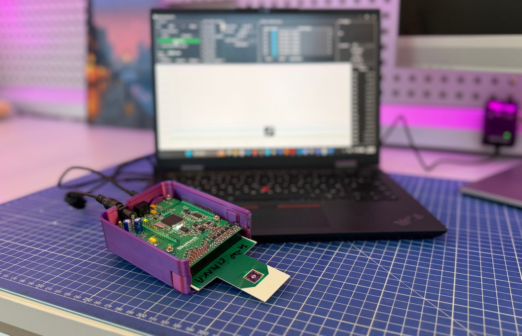
Measurement system for a multi-channel sensor array: analog front end, heater control, firmware, USB exchange, calibration and a PC application.
The device had to acquire signals from high-impedance gas sensors, control temperature and give the researcher a practical tool for setup, calibration and data recording.
A working measurement platform was assembled: sensor array, analog front end, microcontroller, digital processing, USB protocol, GUI, logging and calibration work in one practical loop.
Project materials
Engineering context
17 logical gas channels and two temperature channels.
High-impedance sensors required several transimpedance amplifier ranges.
Heating needed feedback control, PI regulation and temperature slew-rate limiting.
A continuous PC connection over USB CDC was required.
Work done
Analog front end and measurement-channel switching.
STM32 firmware for ADC/SDADC polling, filtering, calculations and heater control.
Lightweight binary protocol over USB CDC.
Flash storage of settings, LUT and operating parameters.
PyQt6 PC application for graphs, logging and calibration.
Details
The firmware switches channels, collects ADC and SDADC data, filters the measurements, accounts for reference readings and calculates final values. In normal operation the PC data stream runs at 20 Hz while the internal polling logic works faster.
The application connects to the device as a virtual COM port, displays channels on graphs, shows temperatures and errors, changes gain maps and extended parameters, logs data to CSV and performs temperature-channel calibration.
Contact
Contact us by email. We discuss custom electronics and automation tasks remotely with companies, labs, small businesses and individual customers worldwide.