Skip to content
Mobile CNC wheel lathe for turning locomotive wheelsets

Projects / Special equipment and demanding operating conditions
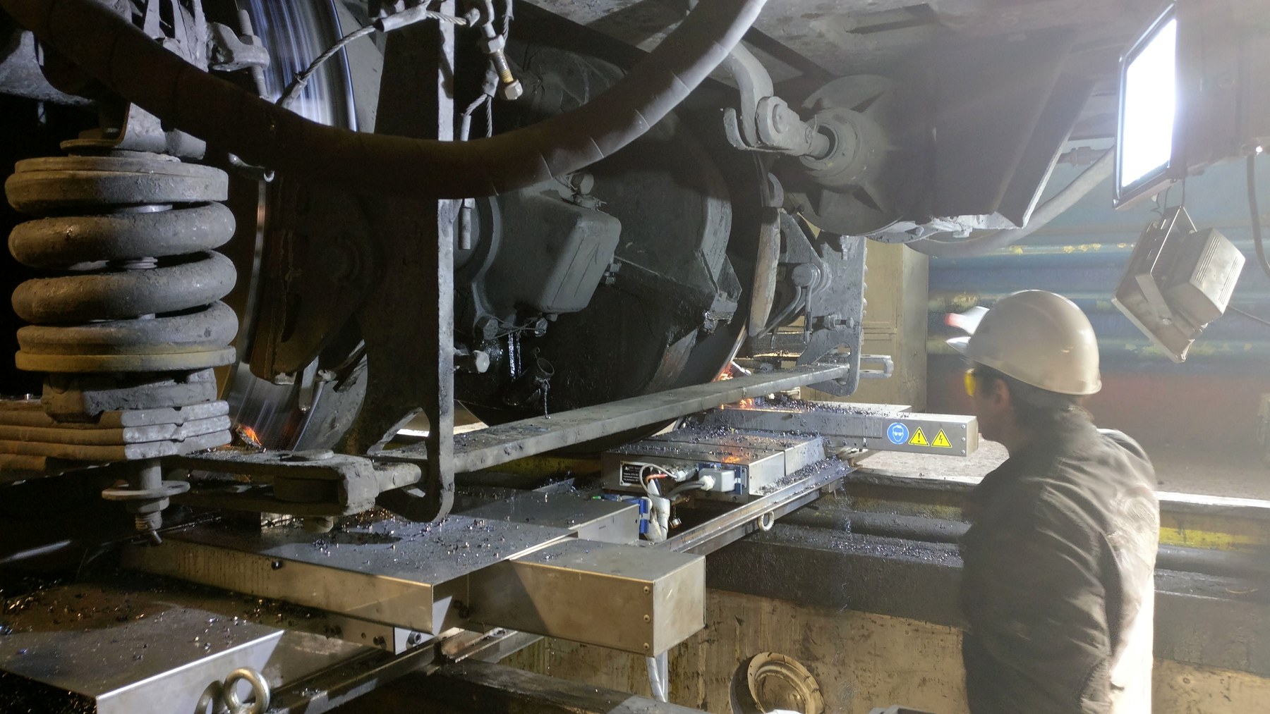
Mobile CNC wheel-lathe control system

Mobile CNC wheel-lathe complex for railway wheelsets: mechanics, control cabinet, STM32 CNC controller, Qt operator software, remote pendant and rotation power unit.

Task

What had to be solved

The task was to create an industrial mobile complex that can be installed on rails in a depot and machine a wheelset without removing it from the locomotive or wagon.

Result

What the project reached

The project was brought to an industrial prototype and pilot operation. The solution is covered by Russian utility-model patent RU 180336 U1.

Mobile CNC wheel lathe for turning locomotive wheelsets
Mobile CNC wheel lathe interface for turning parameters

Project materials

Photos and working materials

Mobile CNC wheel lathe work-sheet interface
Mobile CNC wheel lathe operating interface during turning
Mobile CNC wheel lathe photo interface
Mobile CNC wheel lathe during turning work in a depot
CNC control unit of the mobile wheel lathe
Cutting tool turning the wheel
Mobile CNC wheel lathe during another turning operation in a depot
Manual coolant supply. Automatic mode was planned for later versions
Turned wheel
Internal CNC control units of the mobile wheel lathe
Detailed internal view of the CNC control unit in the mobile wheel lathe
General-view drawing of the mobile CNC wheel lathe
3D view of mobile CNC wheel lathe installation into a pit
3D view of the mobile CNC wheel lathe
Side 3D view of the mobile CNC wheel lathe
Rear view of the mobile CNC wheel lathe in the workshop
Side view of the mobile CNC wheel lathe in the workshop
Assembly of two supports of the mobile CNC wheel lathe in the workshop

Engineering context

Important constraints

The equipment works in repair-depot conditions.

The machine controls four feed axes: X1, Y1, X2 and Y2.

The left and right wheels of one wheelset can be machined synchronously.

Operator workflow includes manual modes, safety logic, reports and repeatable setup procedures.

The project combines mechanics, power electronics, embedded control and desktop operator software.

Work done

What was included

Machine mechanics, production materials and documentation package.

Control cabinet, connection of drives, sensors and safety circuits.

STM32 CNC controller with a GRBL-based firmware adapted for four axes.

C++/Qt operator software with touchscreen workflow, G-code generation and reporting.

Remote pendant for manual movement and machine-control operations.

Inverter-based wheelset-rotation unit with external encoder feedback.

Commissioning support and pilot operation in repair-depot conditions.

Details

Engineering project description

System architecture

The complex consists of two mechanical machine sections with tool carriages, a control cabinet, a CNC controller, touchscreen operator software, a remote pendant, a reporting system and a separate inverter unit for rotating the wheelset.

The machine is installed directly on the rail track under a locomotive or wagon and is fixed to the rails. The design had to account for real depot conditions: metal chips, moisture, coolant and mechanical impacts were important constraints for the protection of guides and moving parts.

Mechanics and four feed axes

The mechanical part is split into left and right base frames. Each side has its own carriage with longitudinal and transverse feed. The four controlled axes X1, Y1, X2 and Y2 make it possible to set different cutting depths for the left and right wheel and machine both wheels of one wheelset at the same time.

  • linear guides, ball screws, servo drives, gearboxes and belt transmissions
  • rail fixation using clamps, stops and spacer elements
  • protection of guides and screws from chips, moisture and mechanical impact
  • production package with 3D model, parts, specifications and drawings

CNC controller and operator software

A custom STM32-based CNC controller was developed for the machine. The firmware is based on GRBL 1.1, ported and adapted for four axes.

The C++/Qt operator software stores profiles and jobs, checks machining parameters, builds the G-code program, shows coordinates and trajectories, controls start, pause, stop and manual movements, and generates reports after the operation.

Trajectory generation

The operator does not write G-code manually. The software builds the motion program from the selected profile, operation mode, bypass direction, feed, cutting depth and wheel parameters.

  • full-profile machining
  • removal of circular build-up
  • flange machining
  • roughing and finishing passes
  • working-area limit checks

Machining workflow

The operator installs the machine, fixes it on the rails, connects cables, references the axes, starts wheelset rotation, brings the carriages into position and sets machining parameters. During automatic operation the screen shows the trajectories, coordinates, feed rate, active pass and execution state.

After machining, the operator can make control measurements and either finish the job with a report or return to an additional pass without losing the current coordinate and referencing state.

Remote pendant

The remote pendant allows the operator to select an axis, move the carriage, change movement coefficient, control feed, start and stop execution, pause the program, switch coordinate displays and control wheelset rotation.

Wheelset-rotation power unit

A separate inverter-based unit was developed to rotate the wheelset during machining. It maintains the required rotational speed using an external encoder pressed against the wheel rim. The module includes enclosure materials, power circuitry, controller circuitry, firmware and production files.

Contact

Discuss your engineering task

Contact us by email. We discuss custom electronics and automation tasks remotely with companies, labs, small businesses and individual customers worldwide.