What had to be solved
The project required controlled electrolyte pumping using stepper motors as part of a laboratory energy-storage setup.
Projects / Industrial automation and embedded control
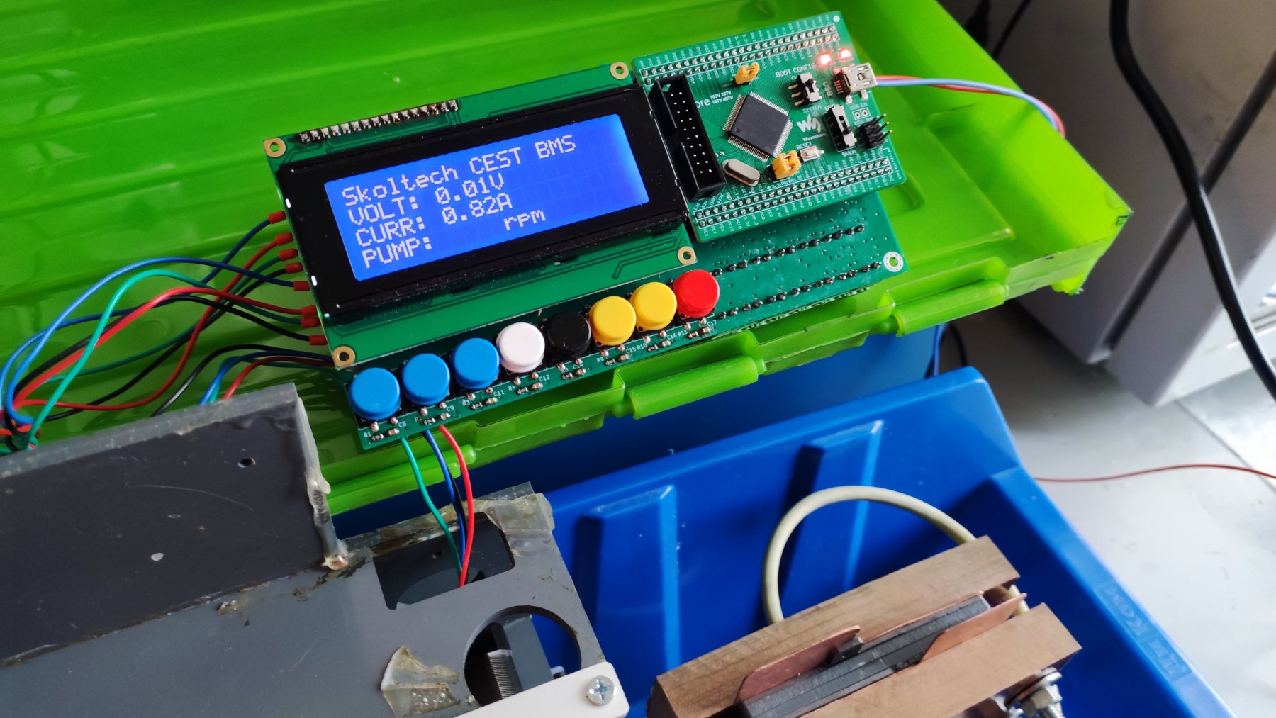
Control board for stepper-driven pumps in a laboratory flow-battery setup.
The project required controlled electrolyte pumping using stepper motors as part of a laboratory energy-storage setup.
A pump-control board was prepared for integration into the flow-battery bench.
Project materials
Engineering context
Pump control is linked to the battery test procedure.
Stepper control allows repeatable flow behavior.
The board had to integrate with other test-bench electronics.
Work done
Stepper pump control circuitry.
Interface and power design.
Firmware direction for pump operation.
Bench integration support.
Contact
Contact us by email. We discuss custom electronics and automation tasks remotely with companies, labs, small businesses and individual customers worldwide.