Skip to content
Control board for a small flow battery

Projects / Measurements, sensors and data acquisition
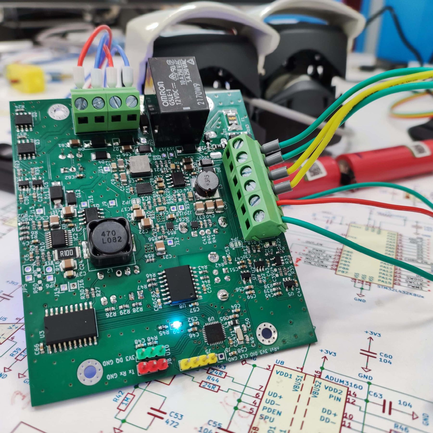
Flow battery control board

Laboratory flow-battery controller for electrical and hydraulic parts: pump control, charging, DC/DC conversion, output switching, bidirectional current and voltage measurement, and USB CDC experiment logging.

Task

What had to be solved

The task was to create a controller for the electrical and hydraulic parts of a laboratory flow-battery setup. It had to switch pumps, manage charging and output connection, measure current and voltage, and send experiment data to a PC for recording.

Result

What the project reached

A working flow-battery controller basis was prepared. The board controls pumps and power nodes, measures bidirectional current, distinguishes external and autonomous power modes, and sends telemetry over USB.

Control board for a small flow battery
Flow-battery control board installed inside the enclosure

Project materials

Photos and working materials

External view of the experimental laboratory flow-battery setup
First prototype of the flow-battery control board

Engineering context

Important constraints

In a flow battery, the electrical mode is linked to electrolyte circulation, so the controller has to consider not only voltage and current but also pump operation.

For a laboratory bench, observability matters: the operator needs to see how parameters change over time and save experiment data.

Pump power had to work both from an external source and from the battery itself.

Some nodes are enabled only in the required modes, reducing manual switching around the bench.

Work done

What was included

STM32L432 control-board circuitry.

Battery-voltage measurement and bidirectional current measurement.

Control of two peristaltic pumps.

Boost-converter, charging and output-switching control.

USB CDC data transfer to a PC.

LED indication, digital filtering, SWD and UART debugging interfaces.

Details

Engineering project description

Device composition

The board combines control logic, measurement circuits, power switches, DC/DC converters, a charging node, USB isolation and pump connection circuits. The result is a specialized controller for an electrochemical bench.

Operating modes

The firmware accounts for external power, battery voltage and pump state. Depending on the mode, the controller can enable charging, disable it at the upper threshold, control the output and send current values to a PC.

Practical value

This type of controller reduces the number of separate wires and bench instruments. The experiment becomes more repeatable because pumps, charging, output switching and measurements work in one logic, while data can be recorded on a computer.

Contact

Discuss your engineering task

Contact us by email. We discuss custom electronics and automation tasks remotely with companies, labs, small businesses and individual customers worldwide.